Author: Adam Heins

Vision Tools #3: Colour Calibrator

This is the third and final part in my series on tools developed to aid in the development of Centaur’s vision system. The previous part can he found here. This post is about a simple application I created to help determine which colours to detect for identification of pipe markings.

The vision system detects points marked on pipes using a bichromatic colour detection algorithm. The algorithm searches for two different colours next to each other in order to positively identify a marking. A major difficulty in the successful performance of the vision system is correctly calibrating the ranges of colour to look for. If the range is wrong, it may miss markings or detect points that are not markings at all. This is particularly risky in a busy environment like the Symposium, where lighting and the colour of the surrounding environment is highly variable.

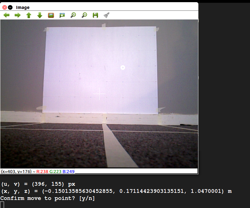
My solution was to develop an application that allows the user to view the Xtion’s feed and select regions that one would like to detect. The application will automatically calculate useful statistics about the region such as the mean, standard deviation, minimum, and maximum pixel values in the region. This application allows one to easily perform calibration in different environments with different lighting conditions without resorting to time-consuming trial and error.

Vision Tools #2: Point Selection GUI

This is the second part in a series of posts I’m writing on the tools developed and used during the implementation of the project’s vision system. The first part was on the physical test setup used to verify the accuracy of vision measurements, and can be found here. After developing the test setup, an easy way to select a pixel from the Xtion’s video feed and generate the corresponding (x, y, z) coordinate was needed. Thus, I developed the Point Selection GUI, pictured below.

Screenshot of the vision GUI viewing the test setup. The user has selected a point and has been asked to confirm it.

The GUI allows the user to view the Xtion’s video stream. Clicking on a point in the image displays both the pixel coordinate and the physical coordinate, calculated using the Xtion’s depth map. Luckily, ROS has a number of packages that handle the modeling of depth-sensing cameras like the Xtion, making the transformation from pixel and depth to actual coordinate fairly straightforward. Once a point is selected, the user can choose whether or not to publish it as a ROS message.

The GUI is useful in a number of ways. First, it us to test the algorithm for mapping pixel and depth readings to coordinates against the physical measurements of the test setup. This is particularly helpful when calibrating the Xtion, because it can be used to verify the accuracy of the calibration. Second, it can be used to test the vision system in conjunction with the robot arm. The user can select and publish a point, first verifying that it is a good destination for the arm’s end effector, and the arm can then attempt to move to that point. This is a core part of the pipe inspection functionality of the robot.


Vision Tools #1: Test Environment

This is the first part in a series of posts I’m writing on the tools developed and used during the implementation of the computer vision system for the robot. The vision system is meant to be able to identify locations on pipes for the robot to measure and provide video feedback for the human operator.

One of the most fundamental parts of the vision system is the ability to map points from pixel coordinates and depth measurements obtained by our Xtion RGBD camera to actual 3D coordinates in the physical world. Luckily, much of this functionality is provided by the OpenNI2 drivers we’re using to interface with Xtion, but calibration is certainly still necessary.

To aid in calibration, I created a physical environment that allows us to place the Xtion at pre-measured physical locations. Thus, we can select a point from the Xtion’s video feed, use the software to map the point to a physical coordinate, and easily see how accurately it matches to the real physical distances to the identified location. An image of the test environment is provided below.

Vision system physical test environment.


The poster board attached to the wall is marked by a grid of points arranged in 10cm squares. Lines have been put down on the floor to indicate 50cm and 100cm distances from the wall, and alignment with 0cm, 40cm, and 70cm from the left side of the grid.

The primary use of the test environment has been to validate efforts to calibrate the Xtion. I have been using the standard checkerboard calibration technique, and have been able to achieve a mapping from pixel coordinates to real-world coordinates that is quite a bit better than the default Xtion settings.

A ROS Node for the Pan-Tilt

I’m in charge of the vision system for Project Centaur. The vision system is responsible for identifying locations on pipes for the robot arm to approach and measure. To accomplish this, we are using an Xtion PRO LIVE, which is a 3D sensor similar to the Kinect. To vastly broaden our possible field of view, we decided to mount the Xtion on a pan-tilt mechanism.

The pan-tilt mechanism that we’re using is made by Robotis, and uses two Dynamixel AX-12+ motors for panning and tilting. An image of it can be seen below. My job was to get it panning and tilting via ROS commands.

To start, I just wanted to get some sort of programmatic control working without using ROS. I found and downloaded the SDK, which is useful in that it provides bindings for many different programming languages. The only practical options here were C++ and Python, since those are what ROS (easily) supports. I chose Python because it’s much faster for prototyping and I just like it a lot better than C++.

I opened up one of the Python examples provided with the SDK. It was quite informative, but it showed that thin bindings to C functions were all the SDK provided. As such, I set out to create a much nicer Python object-oriented interface for the motor. Using my interface, one could easily initialize, shutdown, set speeds, and read and write the pan-tilt values, instead of having to directly write bytes to specific addresses on the motor controller.

With a nice interface complete, the last step was to build a ROS node on top of it. I created a simple node that publishes the pan and tilt angles, in radians, and subscribes to a Twist message for movement. This will allow us to easily integrate the pan-tilt mechanism into the overall system.

The code which I’ve written for the pan-tilt is not currently open-source, but I may post it after further testing.

Interfacing with the R12

The robot arm being used in our project is the ST Robotics R12. The purpose of the arm is to position an ultrasonic sensor against pipes to measure their thickness, thus checking for deterioration. The only software interface provided with the arm was a proprietary Windows client, which allows one to connect to the arm, send commands, and read the responses. However, this software did not cover our needs. The first problem was that we wanted to use ROS for the project, but ROS only runs on Linux. Second, the Windows interface did not provide an easy way to programmatically control the arm. As such, we needed to create our own solution.

Luckily, the Windows client does not do any command processing. The arm is controlled using Roboforth commands, which is a proprietary language developed by ST based on Forth. The Roboforth commands are sent as-is and processed by a microcontroller on the arm itself. The microcontroller sends the resulting signals to a separate digital signal processor which in turn drives the motors. Not having to do any command processing on the client-side, made our job quite easy. I was able to write a simple Python script to open a serial connection with the arm and provide an API to read and write to it. I also created a command-line shell program to control the arm interactively, and bundled it all into a Python package.

The Python package is now being used as a back-end for the ROS node we are developing for the arm. The code for the package is open-source, so I hope that others working with the R12 find it instructive and useful.