This is the third and final part in my series on tools developed to aid in the development of Centaur’s vision system. The previous part can he found here. This post is about a simple application I created to help determine which colours to detect for identification of pipe markings.
The vision system detects points marked on pipes using a bichromatic colour detection algorithm. The algorithm searches for two different colours next to each other in order to positively identify a marking. A major difficulty in the successful performance of the vision system is correctly calibrating the ranges of colour to look for. If the range is wrong, it may miss markings or detect points that are not markings at all. This is particularly risky in a busy environment like the Symposium, where lighting and the colour of the surrounding environment is highly variable.
My solution was to develop an application that allows the user to view the Xtion’s feed and select regions that one would like to detect. The application will automatically calculate useful statistics about the region such as the mean, standard deviation, minimum, and maximum pixel values in the region. This application allows one to easily perform calibration in different environments with different lighting conditions without resorting to time-consuming trial and error.
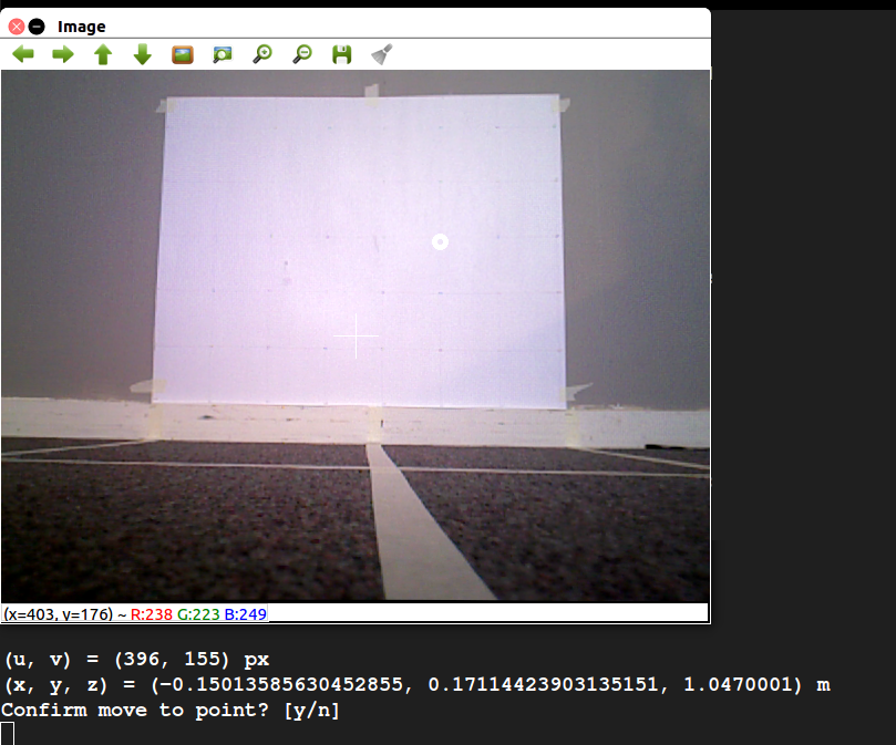
This is the second part in a series of posts I’m writing on the tools developed and used during the implementation of the project’s vision system. The first part was on the physical test setup used to verify the accuracy of vision measurements, and can be found here. After developing the test setup, an easy way to select a pixel from the Xtion’s video feed and generate the corresponding (x, y, z) coordinate was needed. Thus, I developed the Point Selection GUI, pictured below.
Screenshot of the vision GUI viewing the test setup. The user has selected a point and has been asked to confirm it.
The GUI allows the user to view the Xtion’s video stream. Clicking on a point in the image displays both the pixel coordinate and the physical coordinate, calculated using the Xtion’s depth map. Luckily, ROS has a number of packages that handle the modeling of depth-sensing cameras like the Xtion, making the transformation from pixel and depth to actual coordinate fairly straightforward. Once a point is selected, the user can choose whether or not to publish it as a ROS message.
The GUI is useful in a number of ways. First, it us to test the algorithm for mapping pixel and depth readings to coordinates against the physical measurements of the test setup. This is particularly helpful when calibrating the Xtion, because it can be used to verify the accuracy of the calibration. Second, it can be used to test the vision system in conjunction with the robot arm. The user can select and publish a point, first verifying that it is a good destination for the arm’s end effector, and the arm can then attempt to move to that point. This is a core part of the pipe inspection functionality of the robot.
Following up on the goals for reading week (Feb 20 – Feb 26):
Major Goals for Reading Week:
Complete machining of robot lift, robot enclosure, and supporting brackets to assemble by the February 27th
Complete integration of vision system with robot
Implementation of LIDAR safety systems and real world testing
Tuning of drive PID controller with load on the wheels
Integration and final wiring on February 27th
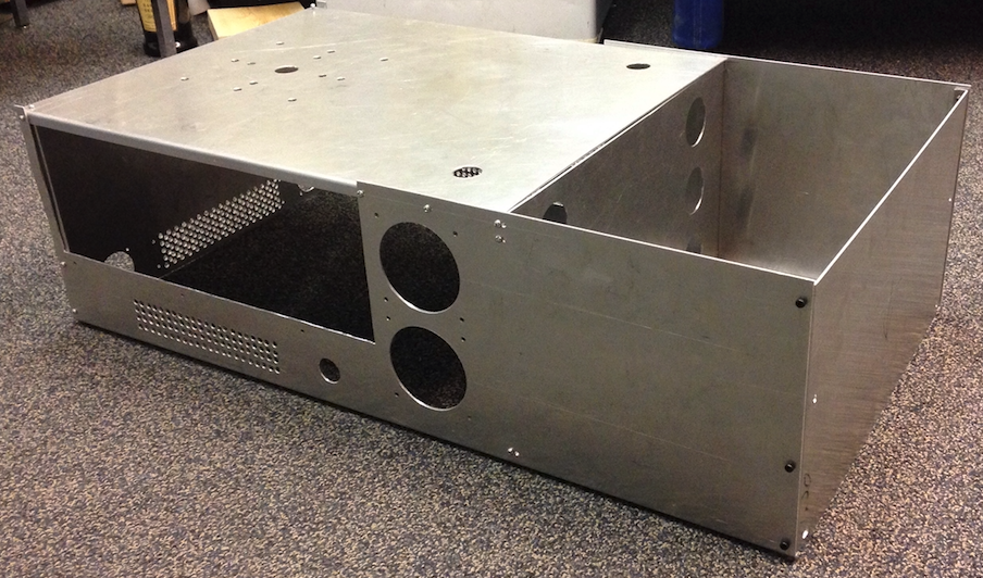
The project has fallen behind schedule mainly due to the machining of the robot lift, enclosure, and supporting brackets taking much longer than expected. After 11 days of an average of 8 hours of machining, the lift is done pending final tests, the robot enclosure has only a few more holes to drill, and the supporting brackets are complete. However, this heavy delay has blocked electrical work requiring the assembled robot to complete wiring.
As the team lead and project manager, I am finding it hard to keep the project on track given these delays and many courses having big deliverables around the same time. For the first time in the project, the weekly Sunday work session reserved for group work and integration is being canceled due to the busy schedule of group members and the mechanical work blocking further progress.
There are 10 more working days (not including Sunday). The new deadline for mechanical assembly has been extended to end of the day on Monday, March 6th. This is the third extension and probably the last one we can afford to do while making the symposium deadline.
Here are some updates of the mechanical components:
This week was our reading week which meant that all classes were canceled and the group got to dedicate a lot more time towards the project. The team set a few major goals for reading week as follows:
Major Goals for Reading Week:
Complete machining of robot lift, robot enclosure, and supporting brackets to assemble by the February 27th
Complete integration of vision system with robot
Implementation of LIDAR safety systems and real world testing
Tuning of drive PID controller with load on the wheels
Integration and final wiring on February 27th
Since the individual components are more complicated, the detailed overview of each part will have their own blog posts coming up. In terms of the overall progress for each of the goals.
Condensed Updates:
Machining took longer than expected, even with 3 group members working on machining actively during reading week, machining of the lift, chassis, and supporting brackets have not yet been completed but it is scheduled to be completed by March 1st.
Vision system integration was successful with robot arm, vision system can identify a point and the robot arm motion planner creates a path to the point. Further calibration is required but the two systems are able to communicate using ROS.
Navigation LIDAR safety algorithms were implemented using simulations, real world testing has begun but is not complete
PID drive system has been tuned with load, will need to tune again once the mechanical assembly is fully complete
Integration is behind schedule and has not started as of Feb 27th
On the Radar:
There are three weeks left for the project, I will be watching the machining closely, the parts need to be finished by March 1st.
This is the first part in a series of posts I’m writing on the tools developed and used during the implementation of the computer vision system for the robot. The vision system is meant to be able to identify locations on pipes for the robot to measure and provide video feedback for the human operator.
One of the most fundamental parts of the vision system is the ability to map points from pixel coordinates and depth measurements obtained by our Xtion RGBD camera to actual 3D coordinates in the physical world. Luckily, much of this functionality is provided by the OpenNI2 drivers we’re using to interface with Xtion, but calibration is certainly still necessary.
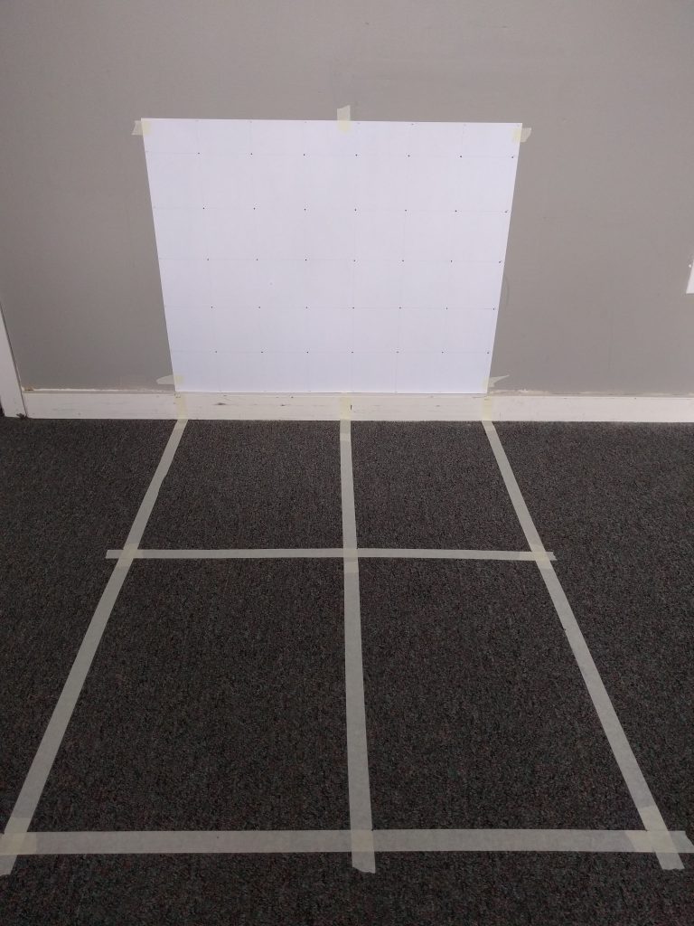
To aid in calibration, I created a physical environment that allows us to place the Xtion at pre-measured physical locations. Thus, we can select a point from the Xtion’s video feed, use the software to map the point to a physical coordinate, and easily see how accurately it matches to the real physical distances to the identified location. An image of the test environment is provided below.
Vision system physical test environment.
The poster board attached to the wall is marked by a grid of points arranged in 10cm squares. Lines have been put down on the floor to indicate 50cm and 100cm distances from the wall, and alignment with 0cm, 40cm, and 70cm from the left side of the grid.
The primary use of the test environment has been to validate efforts to calibrate the Xtion. I have been using the standard checkerboard calibration technique, and have been able to achieve a mapping from pixel coordinates to real-world coordinates that is quite a bit better than the default Xtion settings.
“The Engineer of the Future Trust was launched by Terry Cunningham, in June 2013 on the 30th Anniversary of his graduation with a BASc (Mech, ’83) in Menlo Park, California. The President of EVault™, one of the world’s premier on-premise software and offsite cloud services for data protection and a proud ambassador for Waterloo Engineering in Silicon Valley, Terry kickstarted the Engineer of the Future Trust with a $100,000 gift and a challenge to alumni to match his donation.
With the support of our alumni in Canada and abroad, the Dean of Engineering has created a first in Canada – the Engineer of the Future Trust – a pool of discretionary micro-seed funding for budding entrepreneurs at Waterloo Engineering.”
Project Centaur has received $1,000 of funding from the Engineer of the Future Trust Fund. The team would like to thank the trust fund committee for our reviewing our application and ultimately finding interest in supporting our goals. We will continue to work away on our first prototype and the support will go a long way.
There is an age-old problem in multidisciplinary teams that require integration of software, mechanical and electrical components. The process of designing the mechanical and electrical systems often hinders the development of the software systems involved. In my experience in the University of Waterloo Mars Rover team, this is an issue I personally had faced before and was keen on avoiding during the development of Centaur.
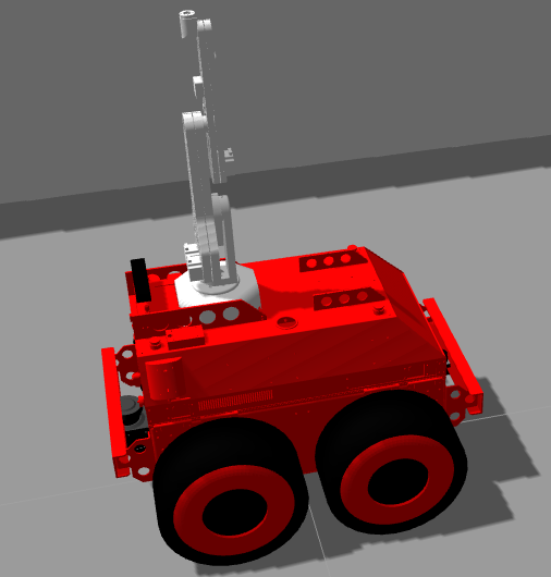
As soon as Project Centaur was kicked-off, Wesley and I discussed using the Gazebo Sim tool provided in the standard ROS installation, such that we could simulate the mechanical apparatus and the sensor systems that will be found on the real robot. The existence of the simulated robot would allow for the parallel development of a lot of the software that will be live on our robot before the robot is actually built.
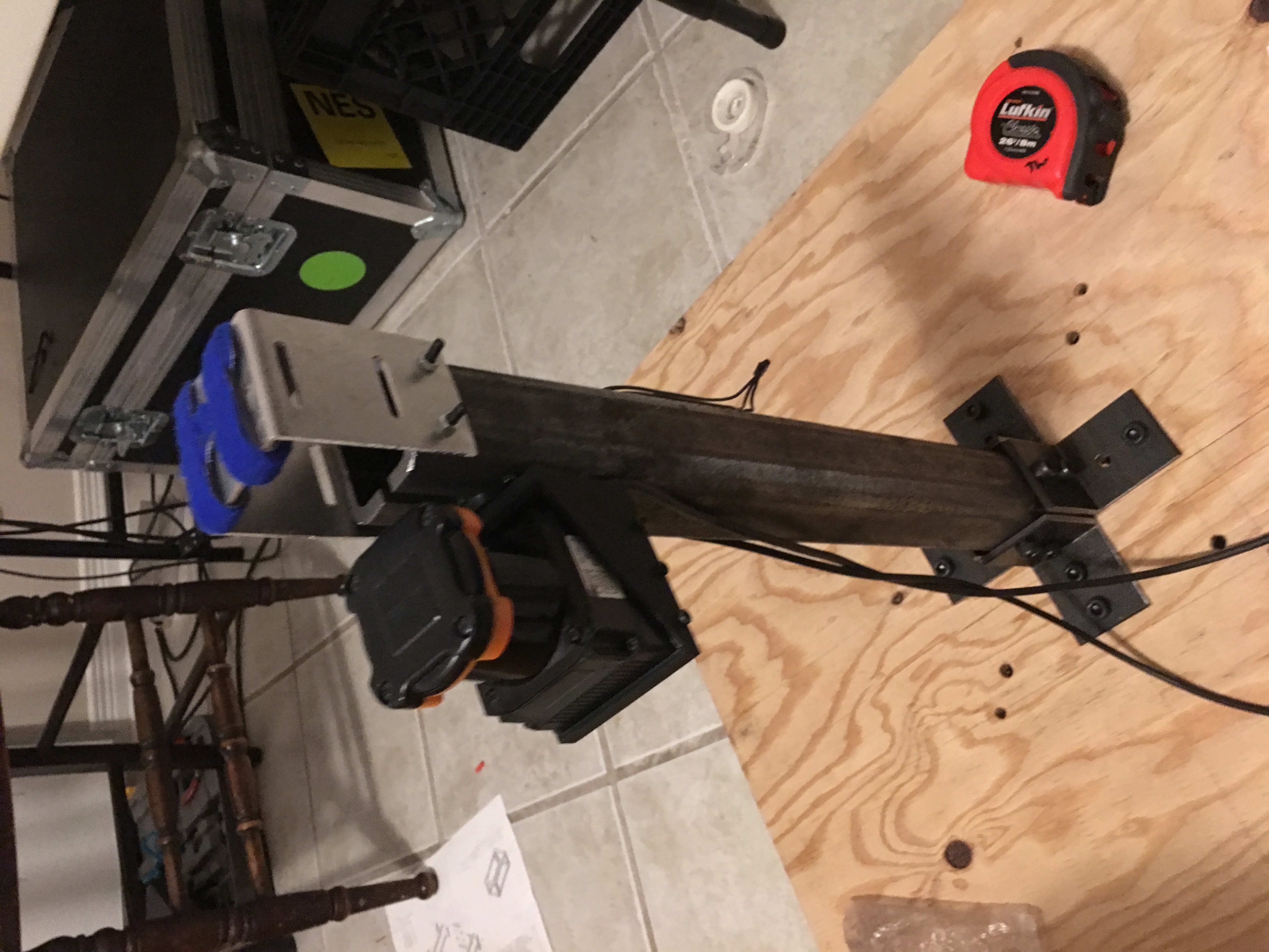
By importing the appropriate STL files and coding the physical properties of our robot using XML markup ( the language of the robot description files), we were able to produce a simulated robot in a short time span. Initially, my task was to outfit the robot with sensors that would allow the operator to move the robot in the boiler rooms without crashing into the robot and validate their positioning. It was decided that two LIDARs in the front and back of the robot would allow for accurate detection of the objects surrounding the robot. The back LIDAR specifically would safely allow for the robot to be reversed by the operator.
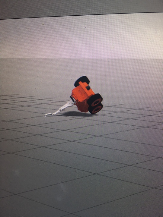
We learned that gravity matters in simulations too
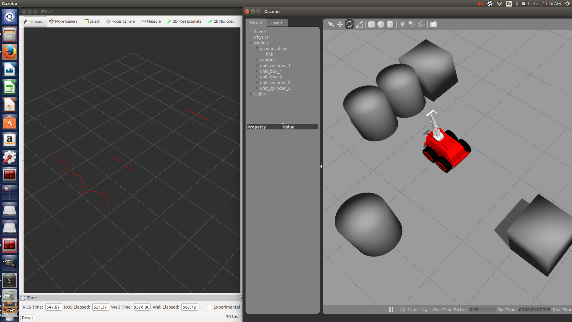
Using the simulation and pulling the open source packages available for both the Hokuyo and the SICK-LMS, I was able to not only simulate the physical model of the sensors, but their sensory output as well. Both LIDARs were publishing the appropriate scan topics that can be used for easy interfacing with our software.
With the simulations displaying the appropriate sensory data, it was time to start development
Tweaking was involved originally in getting the sensors to physically appear as they would in the real robot. This required knowledge of how tf trees (short for transform trees) work in ROS. However, once the sensors were put in their appropriate placements, I was able to start working on the drive safety system that will eventually be used to override operator commands if there is a dangerous object in the way of the robot. Since the drive safety system will be heavily reliant on the front and back LIDAR data, I have been able to use the simulation to test out my code by reading simulated scan data.
For now, the simulation has served its purpose. It will often be reused when it is inconvenient to access the real robot which is constantly in development and has hence, become a handy tool to possess. With the first iteration of the drive safety system nearing completion, I look forward to implementing the safety system on the real robot.
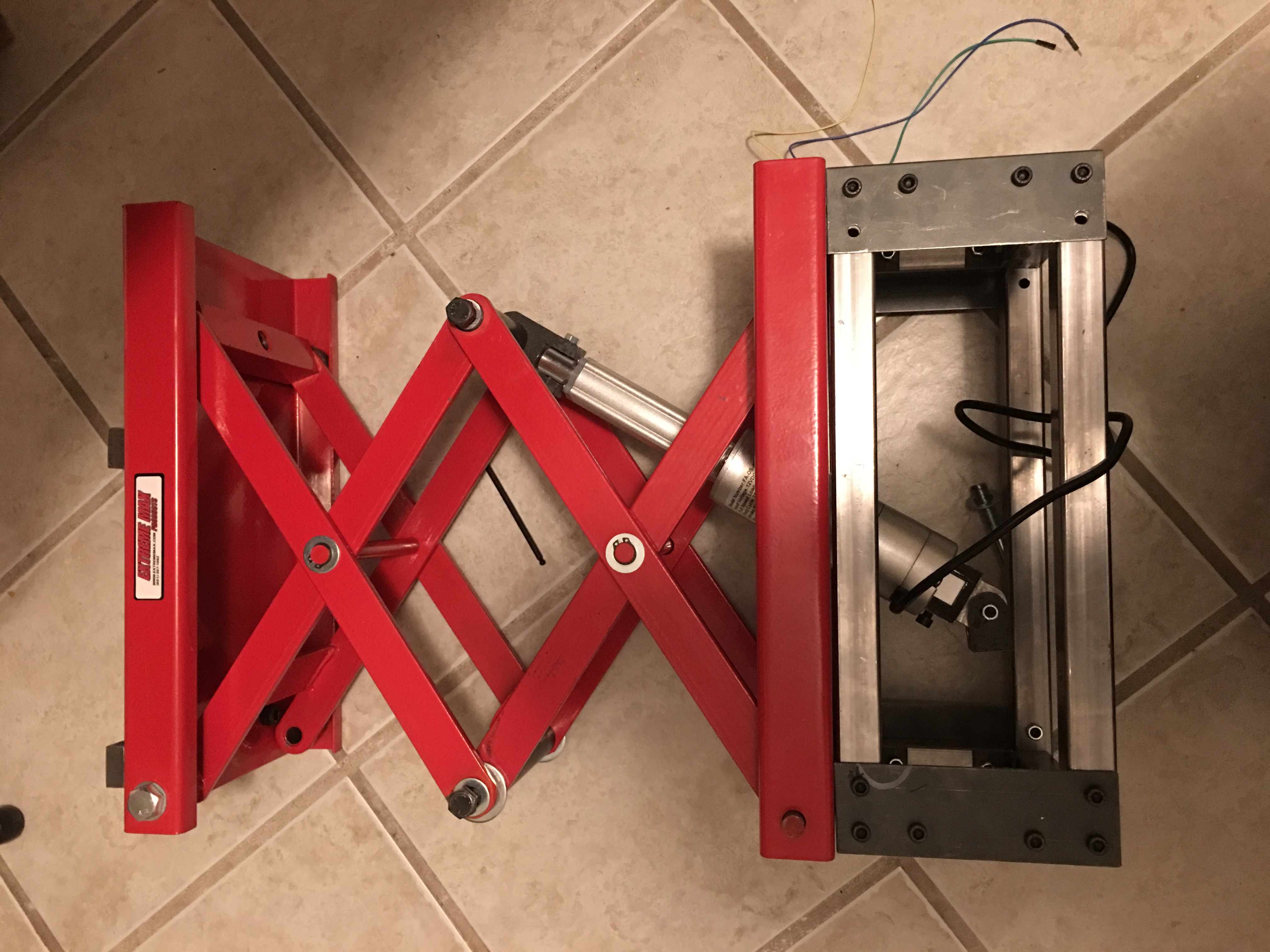
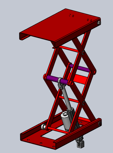
This week, the biggest task on my radar is the robot lift. The robot lift is the component that will extend the robot arm’s height by up to 60 cm. This will increase the size of Centaur’s workspace and enable it to reach more inspection points. The robot lift design has been completed and reviewed.
The robot lift utilizes a linear actuator with feedback control to raise the robotic arm during an inspection. The construction of the robot lift is required to be completed by February 25th, updates will be posted along the way.
Adam is currently working away at developing software for the vision system. A standalone test setup was created to verify the performance of the vision system under the following varied conditions:
Different lighting
Camera angles
Background objects
Adam also developed a GUI to control the pan-tilt and view Xtion feed together.
Wesley is working away at fine tuning and debugging the robotic arm motion planning and control software. Software-enforced joint angle limits are being implemented to constrain the workspace of the robot arm.
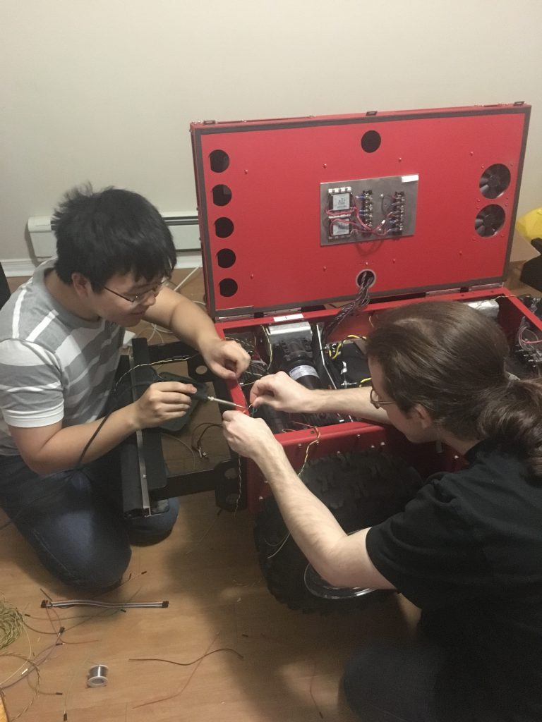
I have been working on cleaning up the wiring in the motor compartment of the robot arm and implementing our charger and voltage monitors. I’ve also been looking into interfacing with our CAN bus controller from Linux.
Rahul developed a ROS node capable for receiving multiple LIDAR data channels and flagging when the close proximity of the sensors has been breached by an obstacle for the safety system.
Centaur is powered using four DC motors with the following specifications
HP: 1/4
Volts: 24
Gear Ratio: 11:1
86.9 in-lbs torque at 168 rpm
In addition the internal gearing of the DC motors, a belt mechanism is used to further gear down the output shaft to increase torque.
The main purpose of the mobile platform is to position the robot arm so that it can reach the pipes for inspection. Speed control of DC motors can be achieved using simple armature voltage control in an open-loop configuration. However, open loop speed control would make it difficult to position the robot. The robot would also not be able to reject disturbances in open loop control such as changes in floor condition. A feedforward PID controller was implemented using optical encoders as feedback.
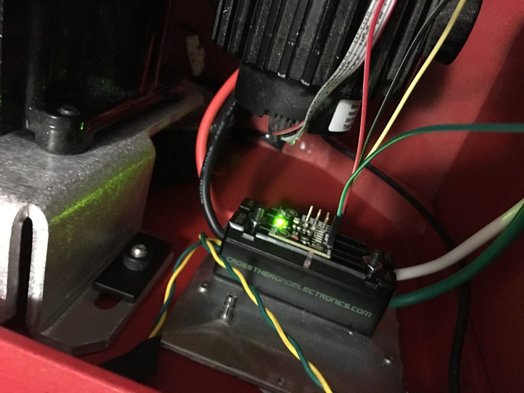
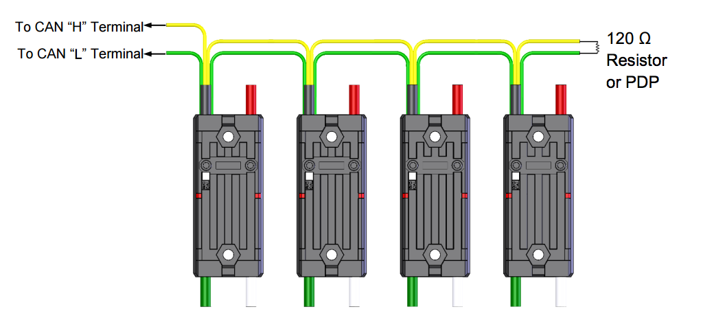
The motor controllers used is the Talon SRX by Cross the Road Electronics. The Talons can be driven using PWM or CAN Bus. With PWM, the motor controllers work in open-loop. However, using CAN Bus, it is possible to connect encoders directly to the motor controller and implement a PID controller directly by programming the TALONs. The benefit of this is motor controls is offloaded from the main controller.
Wiring up the CAN bus was straight forward using a 120 ohm terminating resistor. The only trick was to flash the firmware on all of the Talon’s since the default firmware is for First Robotics Competition and has a token that has to be asserted every 10 seconds.
Further tuning of the PID parameters will be done later this week.
The major milestone for the project is the Mechatronics design symposium on March 17th, 2017. By then it is expected that a functional prototype of Centaur is ready for public demonstration.
In the past few weeks, the team has been busy working towards a few major milestones.
February 20th, Robot Arm and Vision System Integration
Feb 22nd, Drive system calibration with full load
March 1st, System integration and Testing
The goal is by March 1st, all design and construction work has been completed and the remaining time will be spent on integration and writing the software suite.
Here is a breakdown on what each team member has been working on:
I (Eric Shi) have been working on implementing PID controls for our drive system, remote driving, setting up the onboard computer, implementing our power distribution system, wiring everything up in the drive compartment of the robot.
Wesley Fisher has been working on developing the motion planning and simulation package for the robotic arm. He also been working on interfacing with the pipe thickness ultrasonic transducer.
Adam Heins has been working on the vision system that will be used to guide the robot arm. Adam is working closely with Wesley in preperation of integrating the motion planning with the vision system.
Jesse Lopes has been working on the design and fabrication of the lift mechanism for the robot arm. He is finalizing the simulations and will be machining the lift in the next week
Rahul Rawat is simulating the algorithms that be used to help the robot navigate in a known environment using laser scanners