This is the second part in a series of posts I’m writing on the tools developed and used during the implementation of the project’s vision system. The first part was on the physical test setup used to verify the accuracy of vision measurements, and can be found here. After developing the test setup, an easy way to select a pixel from the Xtion’s video feed and generate the corresponding (x, y, z) coordinate was needed. Thus, I developed the Point Selection GUI, pictured below.
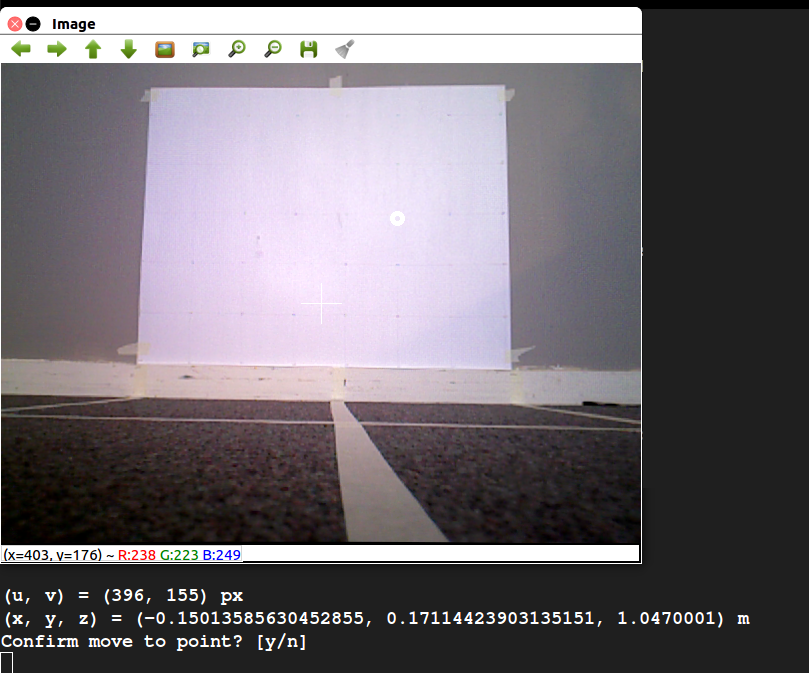
The GUI allows the user to view the Xtion’s video stream. Clicking on a point in the image displays both the pixel coordinate and the physical coordinate, calculated using the Xtion’s depth map. Luckily, ROS has a number of packages that handle the modeling of depth-sensing cameras like the Xtion, making the transformation from pixel and depth to actual coordinate fairly straightforward. Once a point is selected, the user can choose whether or not to publish it as a ROS message.
The GUI is useful in a number of ways. First, it us to test the algorithm for mapping pixel and depth readings to coordinates against the physical measurements of the test setup. This is particularly helpful when calibrating the Xtion, because it can be used to verify the accuracy of the calibration. Second, it can be used to test the vision system in conjunction with the robot arm. The user can select and publish a point, first verifying that it is a good destination for the arm’s end effector, and the arm can then attempt to move to that point. This is a core part of the pipe inspection functionality of the robot.